
BMW M57 EXHAUST MANIFOLD PRESSURE (EMP) SENSOR INSTALLATION GUIDE
A practical guide to measuring exhaust manifold pressure on modified BMW M57 engines, including sensor placement, installation and basic data interpretation
WHAT IS EMP?
Exhaust Manifold Pressure (EMP), also known as exhaust back pressure or EMAP, is the pressure measured in the exhaust manifold before the turbocharger.
Monitoring EMP is especially useful on modified diesel engines, where turbocharger size, VNT control and exhaust flow can have a significant effect on engine performance and reliability.
WHY MEASURE EMP?
- Evaluate turbocharger efficiency
- Detect excessive exhaust restriction
- Improve VNT and boost control
- Compare different turbocharger setups
- Identify excessive drive pressure at high engine speed
- Help optimise compound turbo systems
Boost pressure alone does not show how hard the turbine side of the turbocharger is working. Two setups producing the same boost can have very different EMP.
EMP VS BOOST
A useful way to analyse the system is to compare EMP with boost pressure using the EMP-to-boost pressure ratio.
EMP / Boost = Pressure Ratio
- 1.0:1 – very good
- around 1.2–1.3:1 – generally a good result for a high-performance diesel setup
- significantly above this – may indicate increasing turbine restriction or incorrect turbo control
The ratio should always be considered together with engine speed, boost target, turbocharger configuration and operating conditions.
SENSOR LOCATION
WHERE SHOULD THE EMP SENSOR BE CONNECTED?
EMP should be measured before the turbine, directly from the exhaust manifold or from a suitable pre-turbine pressure port.
The pressure sensor itself should not be mounted directly to the exhaust manifold because of the extremely high exhaust temperature.
USE A PRESSURE TUBE
A metal pressure tube should be used between the exhaust manifold and the sensor. The tube moves the sensor away from the heat source and helps reduce the temperature reaching the sensor.
M57 SENSOR INSTALLATION GUIDE
EMP should be measured before the turbine, directly from the exhaust manifold or from a suitable pre-turbine pressure port.
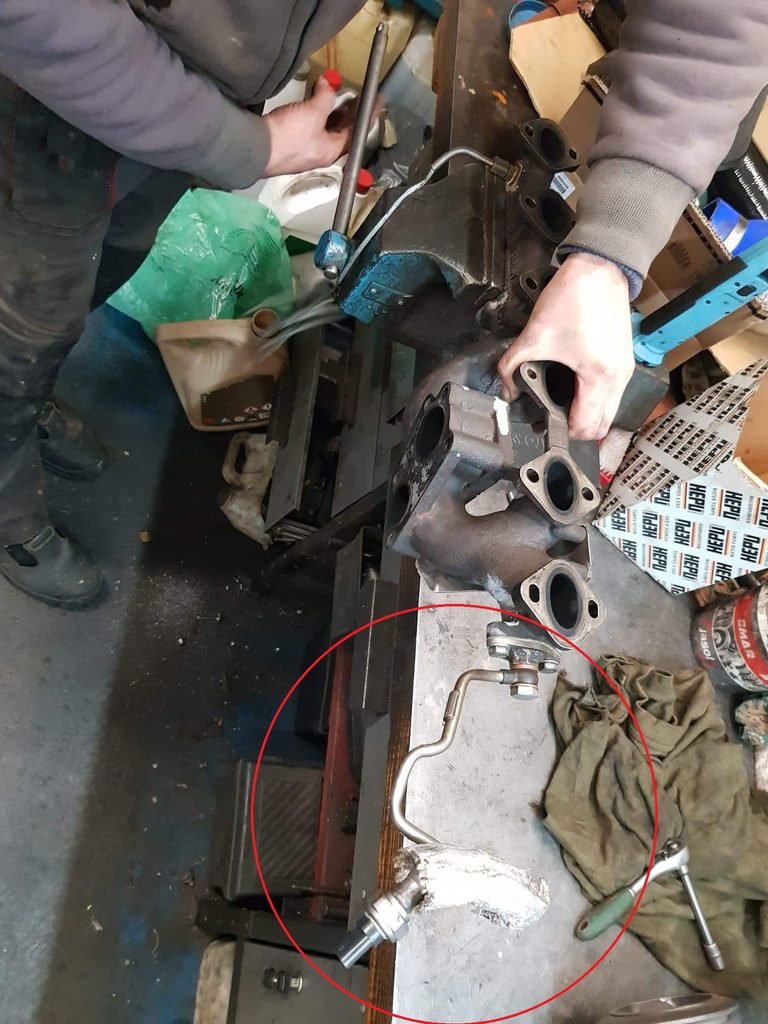
- Select a suitable pressure take-off point before the turbine, as shown in the example photo below.
- Install the fitting in the exhaust manifold.
– EGR blanking plate, drilled and fitted with a welded M12x1.5 nut
– Hollow bolt – 13627811933
– Gasket washers – 2 × 13627811934
– Tube – 13628573973 - Connect the metal pressure tube
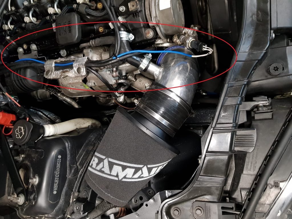
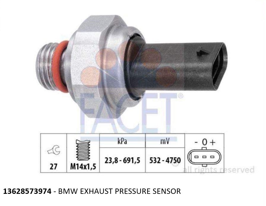
- Position the pressure sensor away from direct exhaust heat. Pressure sensor – 13628573974
- Extend and modify the original DPF pressure sensor wiring. A PDC connector(6934315 – BMW part number) can be used.(the blue wire shown in the photo below)
- Connect the sensor to the ECU
- Configure the correct sensor calibration.
- Verify atmospheric pressure reading before starting the engine.
- Log EMP together with boost pressure,engine speed, boost target, VNT position, fuel quantity, rail pressure.
SENSOR RANGE AND CALIBRATION
The sensor range must be selected for the expected exhaust manifold pressure. A sensor that reaches its maximum measurement range during a pull cannot provide useful data above that point.
HOW TO INTERPRET THE LOG
If EMP rises rapidly while boost remains relatively stable, the turbine side may be becoming restrictive.
On VNT turbochargers, excessive vane closure can also increase EMP significantly without providing a proportional increase in useful boost.
On compound systems, EMP data can help determine whether the pressure balance and control between the turbochargers is working correctly.
THE MEASUREMENTS
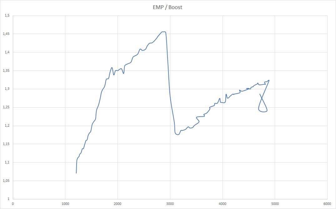
The graph shows the pressure ratio for the BMW 135d described in the Projects section.
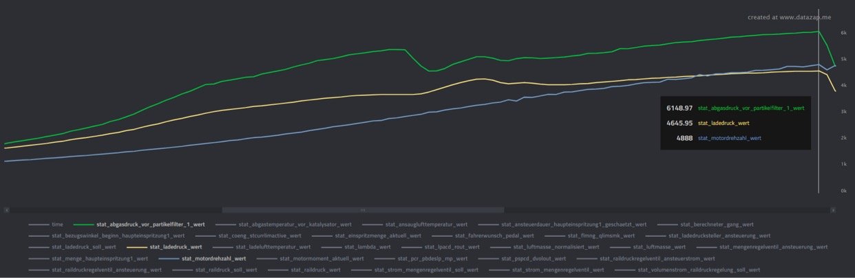
The log shows EMP, boost, and RPM for the BMW 135d described in the Projects section.
FINAL NOTES
EMP is one of the most useful parameters when developing a modified diesel turbo system. It provides information that cannot be obtained from boost pressure alone and makes it much easier to evaluate turbocharger behaviour and optimise the calibration.
DISCLAIMER
This information is intended as a technical reference for experienced engine builders. Incorrect machining or assembly can permanently damage the engine.